Joint Torque Sensors vs. Motor Current Estimation in Robot Joint Actuators: Sensitivity, Bandwidth, Cross-Axis Rejection, and Sizing for Force-Controlled Cobots and Humanoids (2026)
Compare joint torque sensors vs motor current estimation for robot actuators. Check sensitivity, bandwidth, cross-axis errors, and sizing with an RFQ checklist.
Content reviewed: November 12, 2026. This guide is written for robot OEM motion control architects, mechatronics leads, embedded systems engineers, and B2B procurement directors specifying joint actuators for collaborative robots (cobots), force-guided precision assembly arms, medical manipulators, and humanoid limbs globally.
In modern robotics, achieving active compliance, dynamic impedance control, and compliant human-robot collaboration requires continuous, accurate knowledge of joint torques. However, motion control teams face an ongoing architectural debate: should you specify integrated joint torque sensors (strain-gauge spoke rings) at each joint output, or can you rely on proprioceptive motor current (I_q) sensing with model-based friction observers, or use dual-encoder deflection?
Motor current estimation can reuse drive current measurements, but it still requires observer development, calibration, and validation. High-ratio strain wave and cycloidal reducers introduce Coulomb friction, Stribeck breakaway effects, hysteresis, and temperature-dependent losses. These effects can mask small external contacts unless the observer models them adequately. Integrated joint torque sensors measure transmitted torque downstream of the reducer, but add structural compliance, cross-axis sensitivity, electronics, and calibration cost. Neither architecture has a universal sensitivity, bandwidth, or purchase price.
Decision rule: compare the smallest task torque against the mounted system's total error and delay, then check stiffness, combined loads, and the required safety function. This guide provides reproducible sizing examples, a four-architecture comparison, and an eight-point procurement checklist. All numerical examples are hypothetical engineering calculations, not hardware measurements, supplier ratings, or certified contact limits. For a project already at quotation stage, use the Robot Joint Actuator RFQ Template.
Scope: Global English-language guidance for architecture screening and supplier discussions. Industrial collaborative robot safety references do not establish medical-device or non-industrial humanoid compliance; identify the applicable requirements for each application and destination market.
Key Takeaways
- Reducer losses matter: Validate motor-current observers across velocity reversals, temperature, payload, and wear. Gear ratio alone cannot determine the remaining error.
- Sensitivity is an error budget: Resolution, accuracy, zero drift, cross-talk, and residual dynamics are different quantities. Compare them in Nm at the same filtering settings.
- Bandwidth has several meanings: ADC rate, fieldbus rate, measurement bandwidth, and closed-loop force bandwidth are separate specifications. Added sensor compliance changes the mechanical plant.
- Cross-axis rejection needs load conditions: Ask how bending moments and axial forces affect the torque reading with the actual bearing, bolts, and mounting flange.
- Safety belongs to the complete function: A torque sensor, dual bridge, or high update rate alone does not establish a Performance Level or collaborative application compliance.
1. The Physics of Torque Estimation Across the Drivetrain
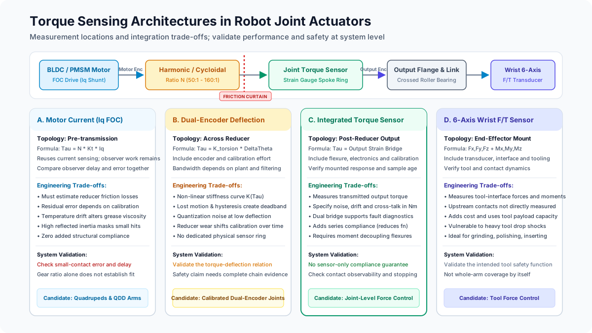
To understand why torque sensing method selection dictates robot capability, examine how mechanical torque propagates from the electromagnetic air gap through the gearbox to the output link.
[Motor Stator & Rotor] ---> [High-Ratio Reducer] ---> [Joint Torque Sensor] ---> [Flange Bearing] ---> [Robot Link & Tool]
     (FOC Iq Sensing)           (Friction Loss)         (Direct Strain Ring)       (Tilting Moments)        (Wrist F/T)
1.1 Motor Current Sensing (Proprioceptive / Virtual Torque)
For a surface permanent-magnet motor driven by Field-Oriented Control (FOC), a model with negligible reluctance torque makes electromagnetic torque at the rotor air gap (τ_motor) proportional to the quadrature-axis current (I_q):
τ_motor = (3/2) × p × λ_m × I_q = K_t × I_qWhere:
K_tis the motor torque constant (Nm/A_rmsorNm/A_peak).pis the number of magnetic pole pairs.λ_mis the permanent magnet flux linkage (Wb).I_qis the torque-producing stator current component.
With speed-reduction ratio N and a lumped forward efficiency η, a steady-state output-torque estimate is:
τ_out,estimate = N × η × K_t × I_qFor a simplified dynamic balance, explicitly represent output-referred inertia and losses instead of applying a lumped efficiency as well:
τ_link = N × K_t × I_q − (N² × J_motor + J_gear,out) × α_out
         − τ_friction,out(ω_out, temperature) − τ_cogging,out(θ_motor)
Model conventions: Match K_t to the drive's peak or RMS current definition; the flux-linkage equation uses a matching amplitude convention. All loss torques and gear inertia in the dynamic balance are referred to the output shaft; α_out and ω_out are output angular acceleration and velocity. Estimate external contact only after also accounting for link gravity and dynamics.
1.2 The Non-Linear Gearbox Friction Model
The friction torque τ_friction in strain wave and cycloidal reducers cannot be treated as a constant scalar efficiency factor. One screening model uses a velocity- and temperature-dependent characteristic comprising Coulomb friction, Stribeck breakaway friction, viscous grease shearing drag, and position-dependent torque ripple:
τ_friction(ω) = [τ_c + (τ_s − τ_c) × exp(−abs(ω/ω_s)^δ)] × sign(ω)
                + σ_v × ω + τ_ripple(θ)
Where:
τ_cis the Coulomb kinetic friction torque.τ_sis the static breakaway friction torque (τ_s > τ_c).ω_sis the Stribeck velocity threshold.δis the fitted Stribeck exponent; the moving-friction model does not fully describe static friction at zero speed.σ_vis the viscous friction coefficient, which must be identified over the intended temperature range rather than treated as a universal constant.
Estimating external contact torque by subtracting nominal dynamics from motor torque leaves residual errors when friction and inertia models are imperfect. Small contact changes can be obscured by those residuals, particularly around standstill and direction reversal. Characterize that uncertainty on the intended actuator: friction magnitude is not automatically equal to estimation error, and improved observers can reduce the residual.
1.3 Direct Joint Torque Sensing (Strain Gauge Transducer)
A dedicated joint torque sensor places an elastic spring element—typically an annular spoke ring instrumented with semiconductor or metal-foil strain gauges in a full Wheatstone bridge configuration—directly between the reducer output and the joint output flange:
Output Reducer (Flexspline/Pinwheel) ===> [Elastic Spoke Ring with Strain Gauges] ===> Output Tool/Link FlangeThe sensor directly measures structural shear strain ε caused by the output torque τ_out:
τ_sensor = K_sensor × Δθ_sensor = C_cal × V_bridge,normalizedWhere:
K_sensoris the torsional stiffness of the sensor ring (Nm/rad).Δθ_sensoris the angular deflection across the sensor flexures; use the rated torque and stiffness to calculate it.V_bridge,normalizedis the bridge output normalized by excitation voltage, expressed in mV/V.C_calis the calibrated conversion coefficient (Nm/(mV/V)).
A sensor downstream of the reducer measures transmitted torque without having to infer reducer losses from motor current. It still measures load acceleration and gravity as well as contact torque. External-contact estimation therefore requires a link-dynamics model, while bearing or seal friction downstream of the sensing element may remain an error source. Confirm the actual mechanical load path rather than assuming all bearings are upstream.
2. Bandwidth, Resonance, and Control Loop Dynamics
A common misconception among purchasing teams is that torque sensing bandwidth is purely determined by the analog-to-digital converter (ADC) sampling rate. In practice, mechanical compliance dictates the dynamic limits of the control loop.
2.1 Series Elasticity and Mechanical Resonance
When a joint torque sensor is inserted into an actuator drivetrain, its torsional compliance acts in series with the reducer's elastic flexspline or cycloidal pins. The combined joint torsional stiffness K_total is:
1/K_total = 1/K_reducer + 1/K_sensor
K_total = (K_reducer × K_sensor)/(K_reducer + K_sensor)
For a hypothetical 100 Nm joint actuator, assume gearbox torsional stiffness K_reducer = 35,000 Nm/rad and sensor stiffness K_sensor = 45,000 Nm/rad. These are example inputs, not measured product specifications:
K_total = (35,000 × 45,000)/(35,000 + 45,000) = 19,687.5 Nm/radInserting the torque sensor reduces the structural joint stiffness by 43.75% in this example.
The natural resonant frequency f_n of the joint driving a link with load inertia J_L = 0.15 kg·m² drops accordingly:
f_no_sensor = sqrt(35,000/0.15)/(2π) ≈ 76.9 Hzf_with_sensor = sqrt(19,687.5/0.15)/(2π) ≈ 57.7 HzThis fixed-drive, single-inertia approximation predicts a 25% frequency reduction, distinct from the 43.75% stiffness reduction. A real joint includes motor inertia, damping, multiple flexible bodies, and a controller; its resonances and anti-resonances require a mounted frequency-response test. Use the example to screen stiffness trade-offs, then tune position and torque loops against the measured plant.
2.2 Bandwidth Comparison Across Architectures
| Quantity to compare | Definition | Evidence to request |
|---|---|---|
| ADC sampling rate | How often electronics digitize a signal | Sampling configuration and anti-alias filtering |
| Measurement bandwidth | Frequency range retained by the sensor chain | Amplitude and phase response at the chosen filter setting |
| Communication rate | Frequency of transmitted data frames | Actual sample age, timestamp behavior, and dropped-frame handling |
| End-to-end latency | Time from mechanical input to controller availability | Worst-case delay including filters, processing, and bus transfer |
| Closed-loop force bandwidth | Response of the mounted controlled mechanism | Frequency-response test with representative inertia and contact stiffness |
| Mechanical resonance | Flexible modes of the actuator and load | Mounted modal data across the payload range |
Motor-current electrical control can be fast while the external-torque observer is limited by model error and filtering. Direct strain measurement removes that particular inference step but still has electronics delay and mechanical resonances. Dual encoders require synchronized angle samples and a calibrated stiffness relation; a wrist sensor needs the complete tool and mounting dynamics considered. There is no architecture-wide 30 Hz ceiling or guaranteed 250 Hz force loop.
For a reproducible delay check, a pure delay of 1 ms contributes 18 degrees of phase lag at 50 Hz: phase lag = 360 × frequency × delay. Filtering and the plant add further phase lag. A 1 kHz bus update therefore does not establish a 1 kHz control bandwidth or a safe stability margin. Request noise and phase measurements together rather than selecting a filter solely for its smoother trace.
3. Cross-Axis Rejection and Structural Load Decoupling
In an articulated robotic arm or humanoid leg, the joint actuator output does not experience pure torsional load (τ_z). As illustrated in our Crossed Roller Bearings Guide, cantilevered robot links exert heavy radial loads (F_r), axial push/pull forces (F_a), and tilting moments (M_x, M_y) directly onto the joint output flange.
       Tilting Moments (Mx, My)
                 \ | /
                  v
[Output Flange] ======= [Crossed Roller Bearing] (Routes bending and thrust to housing)
                  |
         [Decoupled Spoke Flexure]
                  |
     [Strain Gauge Bridge] ---> Calibrated Torsional Measurement (Tau_z)
3.1 The Cross-Talk Matrix Challenge
A raw multi-axis load vector F = [F_x, F_y, F_z, M_x, M_y, M_z]ᵀ acting on the output flange produces mechanical deformations across the sensor structure. If the sensor flexure is a simple flat diaphragm or solid cylinder, tilting moments (M_x, M_y) will stretch the strain gauges unevenly, creating false torque readings on the torsional axis (M_z = τ_z):
τ_measured = S_zz × τ_z + S_zx × M_x + S_zy × M_y + S_zF × F_zHere the moment coefficients are in Nm indicated per Nm applied, while the axial-force coefficient is in Nm/N. For a hypothetical coefficient of 0.03 Nm/Nm and an applied bending moment of 200 Nm, the false torque is 6 Nm. This differs from a specification of 3% of a 100 Nm full-scale torque range, which would mean 3 Nm under the stated test load. A percentage without its reference range and applied cross-load cannot support sizing.
3.2 Mechanical Decoupling Methods
Joint torque sensor designs can reduce cross-axis response through two physical approaches:
- Symmetrical Multi-Spoke Flexure Geometry: By arranging four, eight, or twelve radial spokes with precision wire-EDM flexure cuts, bending moments (
M_x, M_y) create equal and opposite strains on adjacent spoke faces. When wired into a symmetrical 8-gauge or 16-gauge full Wheatstone bridge, the bridge can reduce the response to bending while retaining torsional sensitivity. Manufacturing and mounting asymmetries leave residual cross-talk that must be calibrated and tested. - Structural Bearing Bypass: The actuator's main output bearing can route bending and thrust loads into the housing while the flexure senses torque. The result depends on geometry, mounting stiffness, bolt preload, and the bearing arrangement. Request combined-load calibration in the assembled module rather than assuming a standalone sensor's rejection survives integration.
Specify allowable cross-talk in Nm at named axial, radial, and bending loads. Test both signs and several combinations, including temperature extremes and representative bolt tightening. The ATI force/torque FAQ, sections 2.2–2.5 distinguishes measurement uncertainty, cross-talk, resolution, and latency; those definitions help avoid comparing unlike supplier specifications.
4. Contact Sensitivity and Collaborative Robot Safety
The ISO/TS 15066:2016 catalogue entry identifies its scope as collaborative industrial robot systems, supplementing ISO 10218-1 and ISO 10218-2. It does not establish requirements for every medical robot or humanoid. Verify applicable editions and destination-market requirements for the complete application; an industrial safety reference is not a universal legal force limit.
4.1 Convert Task Forces into Joint Torque Requirements
For a force perpendicular to a joint's lever arm, torque = force × perpendicular distance. More generally, joint torques follow τ = J(q)ᵀ × wrench, with the Jacobian evaluated at the actual contact point. A small moment arm or unfavorable configuration can make a contact difficult to observe through a particular joint.
The following values are hypothetical task forces, deliberately unrelated to human-body contact limits. They show why reach matters when drafting a sensitivity requirement.
| Assumed task force | Torque at 0.10 m perpendicular distance | Torque at 0.30 m | Torque at 0.80 m |
|---|---|---|---|
| 5 N | 0.5 Nm | 1.5 Nm | 4 Nm |
| 10 N | 1 Nm | 3 Nm | 8 Nm |
| 20 N | 2 Nm | 6 Nm | 16 Nm |
| 30 N | 3 Nm | 9 Nm | 24 Nm |
| 40 N | 4 Nm | 12 Nm | 32 Nm |
| 50 N | 5 Nm | 15 Nm | 40 Nm |
4.2 Turn Sensitivity into a Testable Error Budget
Assume a precision assembly task needs to distinguish 10 N at a 0.15 m perpendicular moment arm. The resulting torque change is 1.5 Nm. If the project allocates one third of this signal to total uncertainty, its provisional budget is 0.5 Nm. That allocation is an engineering choice for this example, not a safety threshold.
Suppose candidate A has a measured observer residual bound of ±0.8 Nm across the specified motion and thermal conditions. It would miss this budget even if the drive's current ADC has fine resolution. Suppose candidate B has provisional error allocations of 0.08 Nm filtered noise, 0.12 Nm thermal drift, 0.15 Nm cross-talk, and 0.10 Nm residual dynamics. Their conservative sum is 0.45 Nm, leaving 0.05 Nm for other errors. These are assumed budgets, not results from a tested actuator; calibration uncertainty, hysteresis, and long-term drift must also fit before acceptance.
Use peak bounds for a conservative worst-case sum. Combine errors statistically only when their distributions and independence justify it. Record the motion profile, temperature, filter, mounting, and load conditions with every error claim. Compare candidates against the same requirements rather than treating ADC bit count as contact sensitivity.
For safety-related contact detection, total sensing and stopping delay, force and pressure at the contact geometry, trapping hazards, payload, and robot configuration also matter. Resolving a torque step does not prove a safe stop or a compliant collaborative application.
4.3 Functional Safety Is a System Property
ISO 13849-1:2023 addresses the design and integration of safety-related control systems; its public scope explicitly does not assign the required Performance Level for each application. Determine the required safety functions and PLr through the applicable risk assessment and robot requirements.
Dual bridges can support diagnostics, but shared flexures, temperature effects, power supplies, processing, communication, and mechanical failure can introduce common-cause faults. Category, component reliability, diagnostic coverage, software, and validation evidence must support the claimed achieved PL. Category 3 is not a synonym for PL d, and a dual bridge alone establishes neither.
Ask for the supplier's safety manual, operating restrictions, diagnostic reaction times, and evidence for the complete signal chain. Define the required stop response: Safe Torque Off removes torque production and does not by itself provide controlled deceleration or hold a gravity-loaded axis. Do not infer stopping performance from sensor update rate.
5. Architectural Comparison Matrix: Four Torque Sensing Methods
This qualitative matrix compares measurement locations and integration work. Accuracy, noise, bandwidth, price, and safety capability must come from a named product configuration and its mounted-system tests.
| Engineering parameter | Motor current estimation | Dual-encoder deflection | Integrated joint torque sensor | Six-axis wrist F/T sensor |
|---|---|---|---|---|
| Measurement location | Electrical motor input | Angles across transmission | Output torque load path | Between wrist and tool |
| Primary calculation | Current to motor torque, then dynamics observer | Relative angle through calibrated stiffness relation | Strain through torque calibration | Six channels through calibration matrix |
| Main low-force limitation | Residual friction, motor model, and dynamics errors | Angle error, hysteresis, and stiffness uncertainty | Noise, drift, cross-talk, and remaining dynamics errors | Noise, tool compensation, and mounting errors |
| Reducer friction effect | Must be modeled or observed | Influences transmission behavior | Upstream losses need not be inferred from current | Measures tool load downstream of the arm |
| Bandwidth evidence | Observer response under representative motion | Synchronized angle and torque response | Sensor response plus mounted flexible modes | Sensor, tool, contact, and robot response |
| Added compliance | No additional sensing flexure | No additional flexure if existing encoders are used | Depends on flexure stiffness and integration | Depends on transducer and mounting plates |
| Cross-axis rejection | Load effects appear through mechanical model | Mount deformation can affect angles | Verify at combined flange loads | Verify calibration and combined-load limits |
| Contact coverage | Model and configuration dependent | Model and configuration dependent | Link contacts producing observable joint torques | Primarily loads transmitted through the tool |
| Safety evidence | Validate complete observer and control chain | Validate estimation and control chain | Validate sensor, diagnostics, and control chain | Validate the intended tool-related safety function |
| Cost comparison | Include calibration and firmware validation | Include encoder, installation, and stiffness characterization | Include electronics, calibration, packaging, and diagnostics | Include transducer, interface, tooling, and payload impact |
| Candidate applications | Backdrivable dynamic joints with an adequate error budget | Existing dual-encoder joints with characterized compliance | Sensitive joint-level force and impedance control | Tool assembly, polishing, and multi-axis force tasks |
For quadrupeds or humanoid legs, current estimation may be attractive when transmission losses and model errors fit the task. For gentle hand guidance through a high-ratio reducer, direct output torque measurement is a strong candidate. For precision tool contact, a wrist sensor supplies wrench components that a single joint torque channel cannot. Hybrid architectures are also possible; evaluate the combined benefit against calibration and maintenance work.
6. Sizing and Engineering Trade-Offs
6.1 Mechanical Overload and Shock Margin
A strain-gauge torque sensor is an elastic structural element. Distinguish its calibrated range, permissible operating load, recoverable overload, fatigue limits, and ultimate strength. These are not interchangeable ratings, and combined bending or axial loads may reduce the available margin.
For a simplified undamped rotational impact, energy balance gives:
0.5 × J_eq × ω_impact² = 0.5 × K_total × θ_peak²
τ_peak = ω_impact × sqrt(K_total × J_eq)
Here J_eq is the effective inertia participating in the impact, referred to the same shaft as stiffness and angular speed. Reflected motor inertia may contribute N² × J_motor, but link inertia, contact stiffness, damping, brakes, and control response can change the result. Treat this expression as a screening model, not a crash rating.
As a range-selection example, assume maximum operating torque of 60 Nm and a project-selected factor of 1.5. A 90 Nm measurement range is the resulting preliminary requirement. For a 100 Nm candidate, an allowed noise target of 0.05% of full scale corresponds to 0.05 Nm. This arithmetic does not establish accuracy or mechanical survival; increasing range can make the low-force measurement budget harder to meet.
Request impact duration, combined-load limits, fatigue data, and post-overload calibration criteria. Mechanical stops may protect a flexure, but their loads and clearances are design-specific. A current-based architecture avoids an added sensing flexure, yet its gearbox, bearings, rotor, and drive remain vulnerable to impact. Regenerated energy also requires a verified bus-energy handling path.
6.2 Thermal Drift and Temperature Compensation
Motor copper losses, iron losses, and reducer friction heat a sealed joint. Use the project's measured thermal envelope and the Thermal Derating in Sealed Robot Joints Guide when specifying warm-up and duty cycles.
Separate zero drift, which changes indicated torque at zero applied load, from span drift, which changes the conversion slope. For an illustrative zero-drift coefficient of 0.05% of full scale per 10 K, a 100 Nm sensor over a 40 K change has a 0.20 Nm allocated zero shift. Check whether the coefficient is already compensated, the valid temperature interval, and whether transient gradients are covered. This coefficient is an example RFQ input, not a generic sensor specification.
Temperature sensing and factory compensation can help, but the compensation must represent the installed mechanical assembly. Test cold starts, thermal soak, reversals, and cooling after load removal. Do not automatically tare away an unexplained zero shift following a crash: inspect mechanical integrity and verify calibration first.
6.3 Signal Integrity and Digital Conversion
Small bridge signals can be affected by PWM conductors, grounding, vibration, and cable routing. Placing conditioning electronics near the bridge can reduce the exposed analog path. Compare shielding, excitation stability, anti-alias filters, timestamp synchronization, and error detection rather than assuming one ADC resolution or internal bus is universal.
Specify usable noise at a named filter bandwidth and sampling configuration. Record RMS or peak-to-peak conventions and measurement duration. More filtering can improve the apparent noise floor while increasing delay. Require the electronics, firmware revision, and calibration identifier on every acceptance trace so that a supplier's quieter laboratory configuration is not mistaken for delivered performance.
Before requesting quotations, transfer these conditions into the RFQ template so suppliers price the same measurement range, interface, calibration, and acceptance evidence.
7. Eight-Point OEM Procurement and RFQ Checklist
Use this checklist to define deliverables and acceptance criteria before comparing quotations:
- 1. Measurement topology: Identify the sensing element, its load path, downstream bearings and seals, and whether the deliverable is transmitted torque or an external-contact estimate.
- 2. Range and overload: Provide continuous and peak operating torque, durations, combined bending and axial loads, and expected life. Request separate calibrated-range, recoverable-overload, and ultimate-strength limits.
- 3. Error budget: State minimum task torque and allocate noise, calibration uncertainty, hysteresis, drift, cross-talk, and model residual in Nm. Specify filter settings, sample rate, and the noise convention.
- 4. Cross-axis rejection: Name the applied bending moments and forces for each permitted torque error. Require combined-load results with representative bearing, flange, and bolt preload.
- 5. Thermal conditions: Define temperature interval, gradients, warm-up, and duty cycle. Obtain compensated zero and span drift, calibration traceability, and recalibration requirements.
- 6. Stiffness and dynamics: Request sensor and reducer torsional stiffness, load dependence, mounted resonances, and response traces with representative inertia. Agree on the required closed-loop force bandwidth.
- 7. Safety function: State the risk-assessed safety function, PLr where applicable, diagnostic and reaction-time requirements, and stopping behavior. Obtain relevant safety documentation rather than equating dual bridges with certification.
- 8. Integration and commercial scope: Confirm communication protocol, sample age, timestamping, fault behavior, electrical interface, dimensions, mass, calibration records, prototype lead time, and included engineering work.
For a pilot acceptance test, mount the specified actuator with representative tooling. Apply known positive and negative torques and off-axis loads, repeat after thermal soak, and test the required trajectories against an independent calibrated reference. Record the uncertainty of that reference. Reserve human-contact validation for a qualified application-level procedure; a task-torque bench test is not a substitute.
8. Frequently Asked Questions
Q1: When is motor current estimation sufficient?
When its validated external-torque error, delay, and fault response meet the task across the specified operating envelope. Low-ratio, backdrivable joints often make this easier, but no gear-ratio cutoff guarantees success. High-ratio joints may also use observers if their measured residuals meet requirements. Choose direct sensing when its integration cost buys needed measurement performance.
Q2: Does a dual-encoder joint eliminate a dedicated torque sensor?
Not automatically. Relative angle is θ_out − θ_motor/N; converting it into torque requires a calibrated stiffness relation, consistent sign convention, synchronized samples, and compensation for transmission hysteresis and temperature. See the Dual-Encoder Architecture Guide. Compare measured error with the task budget rather than assuming a universal percentage accuracy.
Q3: How do torque sensors affect servo tuning and repeatability?
A flexure in series with a reducer lowers combined stiffness. In section 2's example, stiffness falls 43.75% while the simplified natural frequency falls 25%. Other designs produce different changes. Tune with the mounted frequency response, then verify stability and tracking across payloads. Compliance alone does not determine repeatability, which also depends on feedback location and control design.
Q4: Can a wrist force/torque sensor replace joint torque sensors?
For some tool-contact tasks, yes. It measures loads transmitted through its own tool interface and is well suited to multi-axis force control. Contacts on upstream links are not directly covered by that measurement path, although they can produce indirect dynamic signals. Joint sensors also have observability limits; neither arrangement alone guarantees detection of every possible arm contact.
Q5: What causes zero drift, and can it always be corrected by taring?
Temperature changes, gradients, electronics, mounting stress, creep, and mechanical damage can shift zero. A controlled zeroing routine can address a verified offset under known unloaded conditions. A persistent shift after overload requires inspection and a calibration check; taring does not restore a yielded flexure or prove its sensitivity remains correct.
Q6: How do sensors survive crash stops?
Only within a verified mechanical protection envelope. Some assemblies use overload stops or other load paths, while others depend on structural overload capacity. Obtain the combined-load and impact specifications for the exact assembly, including whether calibration remains valid afterward. Do not infer survival from an ultimate-strength percentage alone.
Q7: What update rate is required for impedance control?
Choose it from the target loop bandwidth, total delay, noise filtering, and stability requirements. A 1 kHz update is a possible design input, not a universal minimum or a bandwidth guarantee. Determine whether the fast torque loop runs inside the actuator or over the network; specify worst-case sample age and jitter at the controller that closes that loop.
Q8: How much length, mass, and cost do torque sensors add?
It depends on the load path, measurement range, bearing integration, electronics, redundancy, interface, and production quantity. Ask for an assembly drawing, mass breakdown, and an itemized quotation. Compare delivered calibration and validation effort as well as component cost; a current observer also incurs engineering and lifecycle maintenance work.
9. Sources and Methodological Limits
The following public primary references were checked on November 12, 2026:
- ISO/TS 15066:2016 — Collaborative robots. The official catalogue establishes the industrial collaborative robot scope and relationship to ISO 10218. Application-specific contact assessment requires the applicable full requirements and validation procedure.
- ISO 13849-1:2023 — General principles for safety-related control-system design. The official catalogue describes a system design methodology and distinguishes that scope from assigning application-specific safety functions and required Performance Levels.
- ATI Industrial Automation — FAQ: Force/Torque Sensors, March 30, 2020. Sections 2.1–2.5 cover ranges, overload, uncertainty, cross-talk, resolution, and signal performance; sections 3.1–3.3 discuss overload prevention and drift. These definitions inform specification comparisons, not universal ratings for joint sensors.
Methodological boundary: The stiffness, force-to-torque, delay, impact, and error-budget calculations here are simplified analytical examples with stated assumptions. They are reproducible calculations, not first-party hardware tests, independent product comparisons, or supplier quotations. Procurement acceptance requires configuration-specific calibration and mounted-system evidence. No medical-device approval, achieved Performance Level, collaborative-system certification, or destination-market legal compliance is implied.
10. Next Steps for Procurement & Engineering Teams
Selecting the proper torque sensing architecture requires balancing BOM cost, control bandwidth, and human-robot safety compliance:
- Review our Robot Joint Actuator Selection Guide for comprehensive guidance on matching motor frame sizes, gear ratios, and bearing types across 6-axis arms and humanoid manipulators.
- Use the Robot Joint Actuator RFQ Template to compile your required torque capacity, overload margin, cross-axis moment limits, and safety performance level before submitting requirements to suppliers.
- Evaluate our Dual-Encoder Architecture Guide to explore how output encoders complement joint torque sensing for absolute kinematic calibration.
- Explore our Robot Joint Actuator Range, then confirm torque-sensor, encoder, drive, and communication options for the exact module under consideration.
- Send the completed requirements through Contact / Technical RFQ to discuss feasibility, available calibration evidence, and prototype options. Include payload mass, reach, minimum task force, torque-speed duty, thermal envelope, and communication needs so the team can scope an engineering assessment and quotation.
Author

Categories
More Posts
Prototype to Mass Production: 12 Gate Plan for Joint Actuators
A 12-gate execution model for robot joint actuator programs covering prototype validation, CTQ control, compliance file readiness, and production-release criteria with timeline estimates and cost-of-failure analysis.

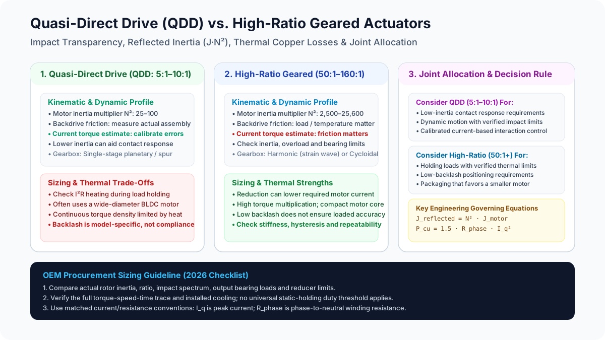
Quasi-Direct Drive (QDD) vs. High-Ratio Geared Actuators in Robot Joints: Reflected Inertia, Impact Transparency, and Thermal Sizing (2026)
Compare QDD vs high-ratio robot joint actuators by reflected inertia, impact response, and thermal sizing. Use the engineering checklist to prepare your OEM RFQ.
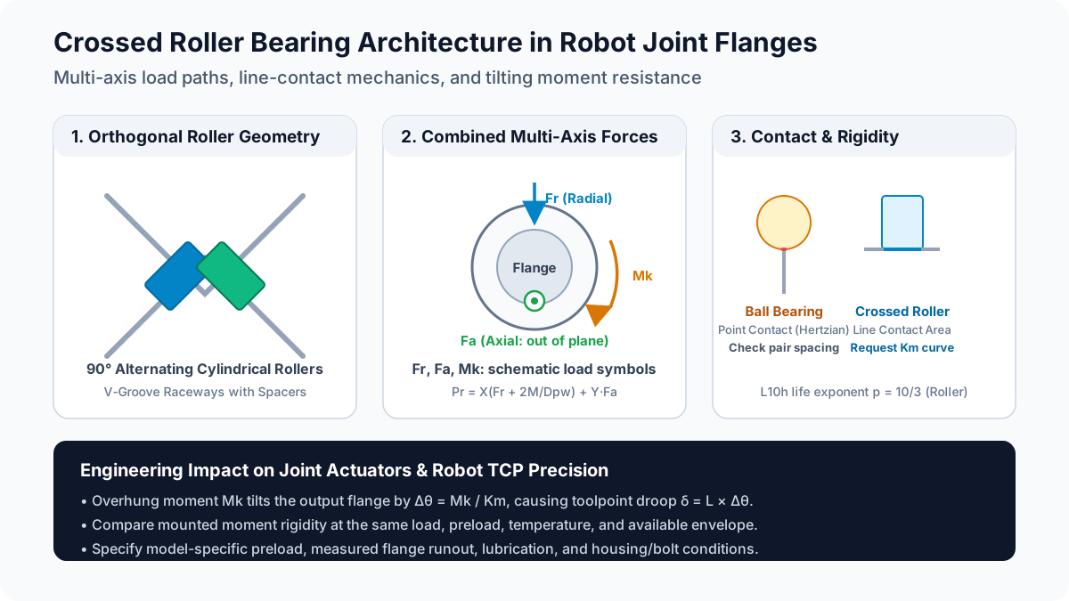
Crossed Roller Bearings in Robot Joint Flanges: Tilting Moment Rigidity, Runout Tolerances, and Overhung Load Sizing
Size crossed roller bearings for robot joint actuators: compare moment rigidity, runout, preload, and overhung loads. Use the engineering checklist for an RFQ.